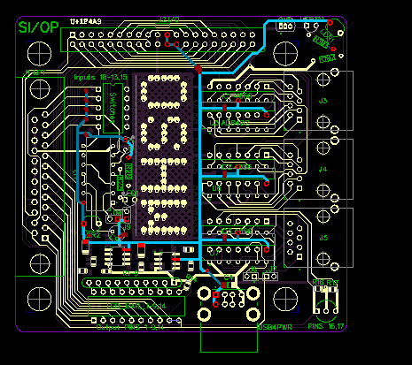
Mounting holes share same size as a standard computer 3.5" case fan.
Board size was picked for maximum amount of PCBs per cost of cutting a single panel.
Round edges for PCB handling.
Lettering of OSHW was deeply integrated with the ground plane in hopes of making harder to remove.
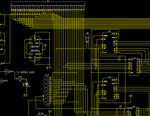
Main design includes some of the following components and why they were chosen:
1. LPT female connector for I/O.
- Enables ability to plug directly into LPT port or via cable.
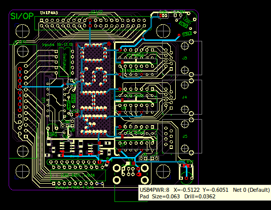
1. Double USB edge connector for power with signals being passed through.
- Even modern cars have an USB port allowing 5V for stand alone circuits.
1. 48 pin dual row connector for sharing signals.
- Common PATA data cable as well as others like the Pi.
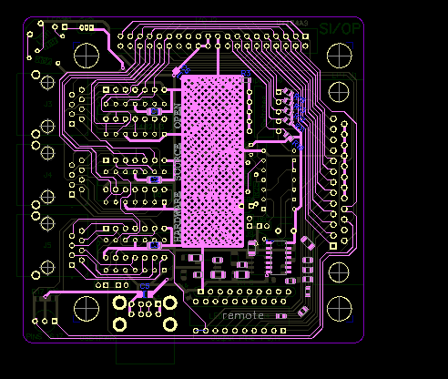
3. RJ45 edge connectors to control a RC by either a 4066 and or AD8402 IC, with selectable clock choice via jumpers.
- Make use of old network cable for clean wiring of remote controllers.
1. 5 switch DIP for testing inputs.
- Solid manual method to test inputs.
1. 10 LED row DIP for testing outputs.
- Size effective for PCB while easy to solder.
1. Bi-pole LED for testing outputs with logic.
- Encourages learning about this device.
Only populate parts of the circuit board which you plan to use, omitting the cost of unused items.
If you only plan to use the circuit to operate a RC and not indicate outputs plus switching the inputs or vice versa, then don't waste time and money on components not required.
The PCB has a basic stand alone NPN transistor circuit for learning. The base being altered via the LDR which is displayed with a LED.
Instead of soldering the LDR flush to the PCB, leaving adequate lead length to bend it towards the LED, can create an on until light is broken sensor.
Also the Schmitt trigger inverter circuit, configured as a relaxation oscillator "wavelength generator", also has a LDR equating variable frequency based on amount of light received.
Which can also be used stand alone or with SI/OP software for an easy analog to digital via taking input of frequency and digital to analog by changing outputs accordingly.
Light LED 1-10 based on amount of light on LDR or set center point to match middle frequency, can also have both colors of bi-LED set for center position and bounce between them.
|
Open Source Hardware
|