|
Logic is what we make of
it, it's as simple as this.
Each logic gate type "AND, OR, NAND, etc..." has
defined rules which are called truth tables. As long as you
follow these rules everything will be logical and work out
correctly.
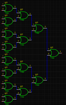
Like an XOR for example, with two thumbs down we get a frown :(, with only one thumb up "either one" we get a smile :), with two thumbs up we get that frown back :(. With the all OR gates circuit, following it's truth table we get a high out if any, or all, of the sixteen inputs go high. This would work well for an alarm circuit monitoring change. Now lets see if you have the logical mind to complete the following: 8to3-encoder.html |
Logic gate truth tables.
All OR gates circuit.
  |
| It's a long way to go
from a switch on the test board to parallel port, processed,
parallel port back to test board and have a LED turn on. Just having hardware switch which people touch and the LED feedback makes the learning more fun for me and hopefully others. Use input pin 15 of lpt0, lpt1 for logic in A & B and pin 17 of lpt2 for X in the following: #Written scripts for SI/OP to emulate standard logic gates via ports input(s) and output. |
||||||
|