|
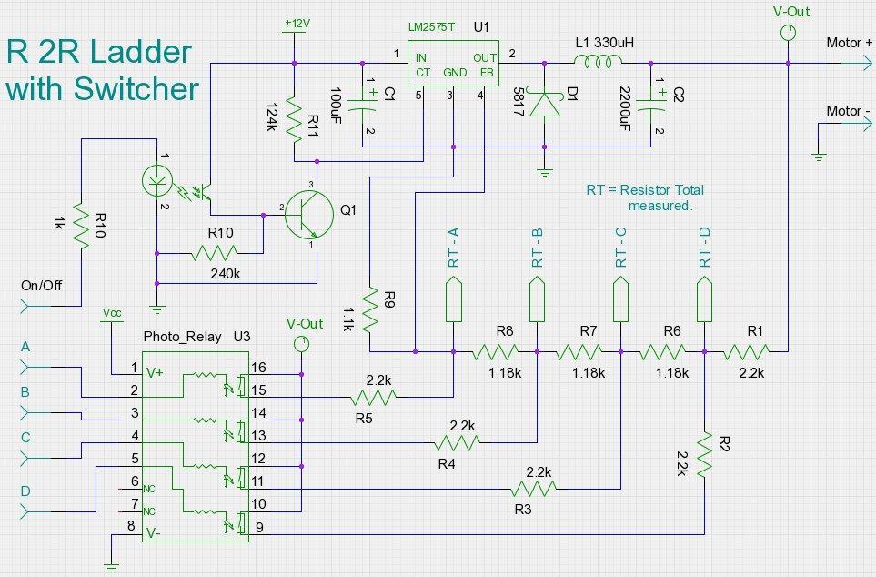
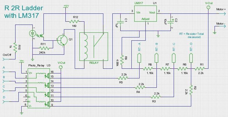
R 2R = Resistors 1 to 3, value is times two for resistors 4 to 8.
 |
Resistor Total "RT" value was measured.
This is showing output of ohm meter, as 2R resistors are switched in and out, from ground reference to RT point with the circle.
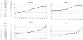
Doing a standard binary count from 0000 to 1111 we get a variable resistor measured from 124.8k ohms to 24.9k ohms. Calculations of:
0000 R4+R3+R2+R1 = 124.6k
1111 1/(1/(1/(1/(1/R4+1/R5)+R3)+1/R6+R2+(1/R7)+R1)+1/R8) = 24.9k
Link to spreadsheet r2r_calculator.ods which you can plug in your own values.
Has been updated for 32 bit.
|
|
|